A Brief History of the AJP / TVR S6
Much has been written about the original design of the TVR Speed Six engine and that Al Melling's design was flawed, so we have decided to set the record straight. We purchased the original designs of the AJP-6 drawings in 2005 and have the invoice to prove it.
In the mid nineties Al Melling of of MCD was asked by TVR to design a new engine for their new car, the engine was designed and six development engines were delivered, and for whatever reasons - which we will not go into now - the design was radically altered. In doing this the engine suffered from reliability and was found to have a lot of wear on the valve guides and finger followers, which was due to valve train geometry being altered from the original design.
We looked at these problems
and contacted Al Melling to discuss possible solutions. It
came about that we purchased the original AJP-6 design blue
prints for the engine from MCD in 2005, and with these to hand we were
able
to have new valves, valve springs, valve guides and finger
followers made. These parts were never fitted in the production
engines, and were manufactured to help correct the valve
train defects for more reliability smother
running.
We also had new tooling made to manufacture our own chilled iron unique wide lobe design camshafts. ( See the blueprints and the write-up that goes with them elsewhere on this web site.) You can then draw your own conclusions about intellectual copyright.
Design differences
The drawings on this page and others that appear on this site are extracts from the actual MCD engineering blueprints, so you can judge for yourselves where the main differences are from the original Melling design.
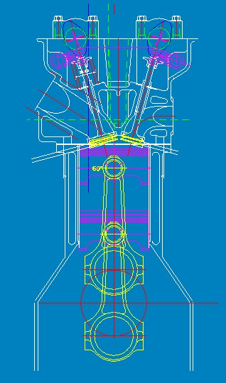
This drawing shows the end view of the engine. This shows the position of the cams and the shape of the finger followers. It is commonly believed within the TVR community that the camshafts were repositioned in the production engines. This however is not the case, and can be seen once you check the original MCD blueprint dimensions against an engine on the bench. The camshaft centreline is directly over the valve stem, so the rocker ratio is 1.3:1. However, TVR did alter the finger follower design which in turn put an excessive side loading on the valve stems, causing guide wear. Something that is exacebated by a reduction in the size of the valve stems, which were reduced from 8mm down to 7mm.
This end on view of the cylinder head shows the detail of the dual oilways on each side of the head. On the right hand side you can also see the oil return to the sump.
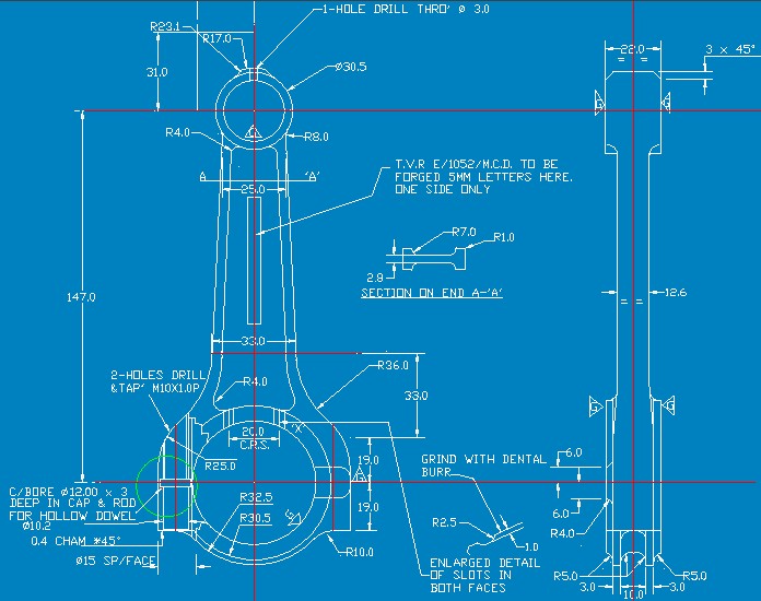
This is the 3.5 litre drawing for the conrod (note: this is not a 3.6 litre rod). The rod is shorter than that on the 3.6, and also the big end journal width is narrower.
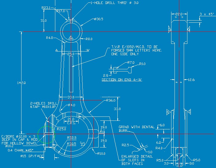
This is the 4.0 litre conrod drawing – as you can see, this is nothing like that that TVR used in the production engine. This rod is correctly balanced, and is shorter. The big end is narrower too than the production 4.0 litre rod.
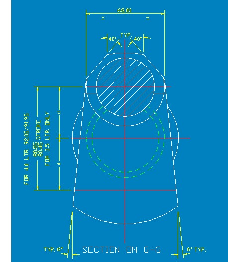
This is the end view of the crankshaft. The original design shows two different strokes – 80.5mm for the 3.5 litre and 92.05mm for the 4.0 litre. On the Speed 6 the conrod big end width is wider. These cranks were fully counterweighted. TVR changed the stroke on the 3.5 litre to 83mm for the 3.6 litre engine.
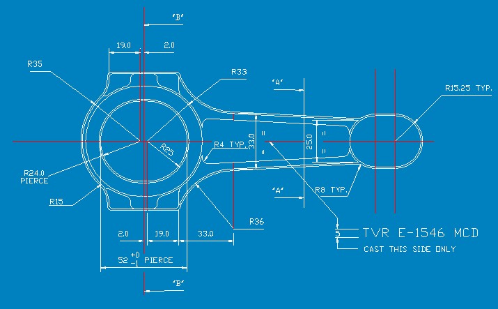
Here is the design drawing for the connecting rod blank forging – i.e. before machining – a good example of 'one size fits all' engineering. Actually the big lump on the small end allows it to be finished to size for any of the TVR engines. This is the rod that ended up in the 4.0 litre. With the amount of extra material provided this rod's little end is actually heavier than the big end!
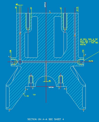
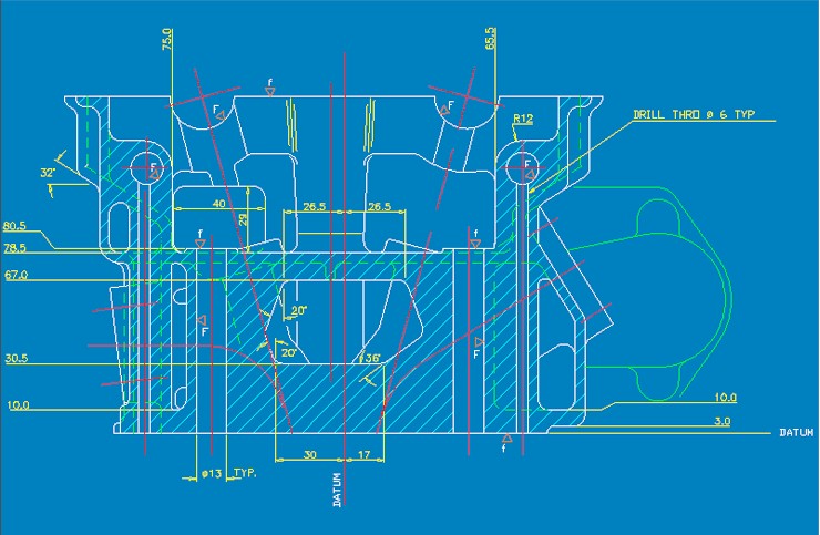
This drawing is an end on view of the block showing the details of the oiling system and the main bearing caps. Key points to note here are:
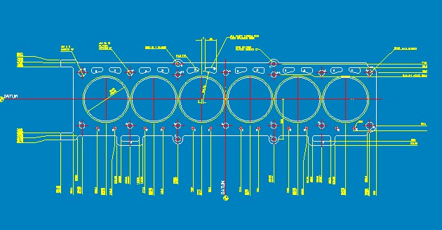
The head gasket – quite a bit different than the stock TVR item. Notice the four oil feeds to the head, the two extensions on the gasket between number 1 and number 2 cylinders, and also numbers 5 and 6. These are oil return passages to allow lubricant to drain back down to the sump on the exhaust side.