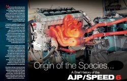
Speed Six General Information
The work that we
have done with the TVR Speed 6 and its derivatives has been exciting,
challenging and technically rewarding, in that we achieved all that we
set out to do (and more....) with our design upgrades, as regards both
enhancing these engines' reliability and their performance.
We therefore invite you to browse through the dyno records,
engineering blueprints and build photos. so as to get a flavour of both the automotive engineering and the industry knowledge
that was needed to create such a world-class series of performance upgrades.
The same expertise, incidentally, that underpinned - and still underpins - the work we undertake on the
American V8 and Ford V6 families of engines, and which you can read about elsewhere on this website.
Contents -
1. Torsional
Vibration and the
Speed Six Engine
One
of the problems with the Speed Six engine is torsional vibration, The
crankshaft is 660mm long from the rear main bearing to the front main
bearing, and the nose is another 127mm on top of that. Total
length is 787mm. This makes for a long crank - 31 inches - in real
money!
Now looking at the two engines, the 3.6 has a stroke of
83mm - or 3.268 inches - and the 4.0 has a stroke of 92 mm - or 3.622
inches. Both engines suffer from torsional vibration, the 4.0 litre
more than the 3.6 because of the longer stroke .
The cause of
this is the rotational mass of crank rods and pistons, which is in two
parts: the crank and the bottom half of the rod (big end) is the
rotating mass, and the top half of the rod small end and piston being a
reciprocating mass.
For
an example of what can happen when things get out of hand, see the
pictures below. Here, a 4.0 litre engine was run up to 7500
rpm
on a dynamometer, and then the throttle butterflies inadavertendly
snapped
shut by the operator..... exactly what happens should you miss a gear
on a downchange.
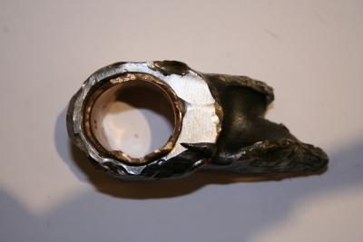
Little
end showing weak point in rod where breakage occurred.
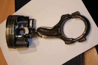
Damaged
components laid out for inspection.
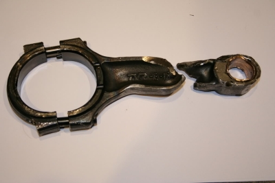
The rod - or what's left of it, after being dug out from the crank
journal
The cylinders are in pairs 120
degrees apart
and are firing as 1 & 6, 2 & 5 and then 3
& 4. As
each pair reach tdc one cylinder will be exhausting, then once over tdc
it will be on induction, whilst the other will still be on compression,
followed by its power stroke once over tdc. On one 360
degree rotation
of the crank each pair of cylinders will go through the above
cycle.
At the bottom end, the Speed Six's main bearing caps are however only
retained by two nuts and studs with locator dowels.
If
you ever have a chance to look at the main bearings from a disassembled
engine, you will see that there are marks on the outer edges These are
caused by the crankshaft moving and twisting under load,
where
the caps move under the torsional stresses of crank shaft rotation at
each pulse of an individual cylinder's compression/ power stroke, plus
the 'braking' effect on the crankshaft by other cylinders on their
exhaust / induction strokes.
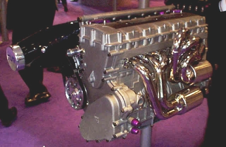
Early
TVR Speed Six re-designed
engine without crankshaft damper:
To try to counteract this
'twisting', TVR followed standard automotive design practice by fitting
a fluid damper to the front of the engine, (actually a small block
chevy part). However, we are still of the opinion that the standard
bottom end remains a weak point of this engine.
Accordingly,
we have developed a revised main cap support modification, comprising
add-on bracing components installed with additional machining so as to
positively locate the caps in horizontal as well as vertical planes.
This both cuts down vibration and strengthens the block in this
critical area at the same time.
2. Boring
and Stroking - how big
can you go?
Whether
it is a Speed 6 or a Briggs and Stratton 4-stroke on a
ride-on
mower - there are only three ways you can increase the capacity of an
engine. By
over-boring the cylinders and fitting matching larger pistons. Using a longer stroke crankshaft
to increase the distance the piston has to travel along the cylinder
bore. By a
combination of both of these.
However,
there are a number of
things you should know before going down any of these routes to gaining
greater power.
To start with, if you
are just overboring your engine, providing there is enough
bore wall thickness to fit the bigger pistons and you have a gasket to
for the larger bore, you will need to adjust ignition and fueling.
If your over bore is over 1mm or .040" thou., how much extra capacity
you will get depends on how long a stroke you have. You can check this
out by using the following formula -
Bore x bore x 0.7854 x
stroke x number of cylinders = capacity
To convert mm to inches
divide by 25.4.
To convert Inches to mm
x 25.4.
When
stroking an engine you have to take into account the following factors: stroke length, rod length, and
piston pin height. The first step after fitting
your
stroker crankshaft is therefore to check the position of the
piston at top dead centre - or T.D.C., as it is known. If you stick with a standard
piston and rod, you will find that the piston will stick out the top of
the block -
so you will need to either machine the piston (only if there is enough
crown thickness to skim it down enough
to give you the correct
compression ratio or valve clearances) or else:
Fit new pistons
with the correct pin height for the new stroke
Use a shorter conrod to
bring the piston down the bore
Do both of the above
Remember, if
the stroke is increased by say
11.8mm or 0.300" thou, you will only need to move the
piston pin nearer the crown by HALF
the extra stroke.
Alternatively, you would shorten the rod by 2.95mm
or 0.150" - or use a
combination
of these two methods to get the compression ratio you need. Now,
by increasing the stroke we also increase piston speed for a
given RPM - because the piston now needs to travel a longer distance,
but in the same time.
Here's an
example. Using the formula -
Piston
speed = stroke in inches
x rpm divide by 6
- we apply this
to an F1
engine with a 40.64mm or 1.6" stroke, which gives
us -
Stroke
of 1.6 inches
x 18000 rpm
Divide by 6 = 4800 ft per minute
Divide by 60 = 80 ft per second (or if you want that in metric, divide
by .3048 = 24.38
meters per second)
These engines
use some pretty exotic materials to
run at these speeds - which
interestingly enough, would also be needed if you increased
the stroke to 3.2 inches but
halved the rpm, since the piston speed would in fact
remain
the same. Though the rpms may have now dropped to 9000, the
inertia shock loads each time the piston reverses direction at the end
of its stroke, plus the need to cope with and dissipate heat that is
built up within the engine through friction and combustion, will
require similar engineering solutions, if the motor is to stay
together.
Talking of friction and
heat, lets turn for a moment and look at rod ratios.
The maths is simple enough -
simply divide
the stroke into the rod length, measured centre to centre from little
end to big end (crank to piston pin).
So, for a 5.7
inch rod, we divide by 3.75
which gives a rod ratio of 1.52.
Which
In our opinion, is just the right side of acceptable. Why? Because once
you go below a ratio of 1.5, the following sorts of issues can all
start to raise their heads -
Side
thrust on the piston is
increased because the rod angle is more acute, leading to
increased wear on the
rings and bores.
Since the piston speed
is faster at top dead centre, cylinder filling is compromised on
overlap.
The pistons can be noisy
- not an issue on a race car, but perhaps a bit wearing on the road.
How does the
TVR Speed Six compare with all this theory? Here are the
factory specifications -
3.6 litre
conrod length is 150mm, with a stroke of 83mm, giving us a rod ratio of
1.8
4.0 litre conrod length is 144.5mm, with a stroke 92mm, yileding a rod
ratio of1.57
For the record, the early 4.0 litre had a shorter conrod, at 142mm long, with a rod ratio of 1.54.
NOTE.
Elsewhere on this site you should find the
technical information on the conrods.
3. TVR
Speed Six
Oil System Upgrade
First
we need to understand the system we have at the moment. The oil is fed
from the header tank to the oil pump, then from the oil pump to the oil
filter on the inlet side of the block through the filter to the main
oil gallery that runs along the inlet side of the block. From the main
oil gallery the oil is then fed to the 7 main bearings to lubricate the
crankshaft, and finally through the crankshaft itself to the big ends.
If
you look at the main bearings you will see one half has an
oil
groove in the part that fits in the block the other half that fits in
the main cap is plain. This means that in the standard engine, as the
crankshaft rotates, oil feeding the big ends is cut off for 180 degrees
of crankshaft rotation. To improve the oil flow, the main caps can be
modified by fitting a grooved bearing in the cap - this allows a
constant oil feed to the big ends and aids cooling as well lubrication.
Turning
to the oiling system in the cylinder head, the oil travels
from
the main gallery up the two oil feeds to the cylinder head on the inlet
side, then goes through the follower shaft on the inlet side
to
the back of the head and stops. The oil also flows forward to the front
of the head, where it crosses over and travels back down the
follower shaft on the exhaust side. This means that the last
part
of the head to get oil is the back of the head. Along the way, the
follower shaft feeds oil to followers and sprays oil on the
camshaft lobes, as well as lubricating the camshaft bearings.
If
you look at each follower, you will see that there is no oil groove in
the centre - so as the follower moves off centre the oil is cut off
momentarily which compromises not only lubrication but the effects of
oil spray cooling to the inside surfaces of the cylinder head.
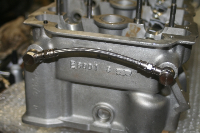
Additional
oil feed to rear of head, as fitted by RND Engineering to its Speed
Six
heads
To
rectify this, RND fit an additional oil feed to the rear of the head on
the exhaust side. When we first looked at this in 2005, we spoke to Al
Melling direct and his suggestion was to up the oil pressure as well,
which goes along way to rectifying the oil feeds that were removed by
TVR in their redesign. Using Al Melling's original design of
finger followers - which are are not only lighter but are the correct
shape to follow the camshaft - which now have a 360 degree
oil
groove added, constant oil flow to the camshaft lobe is
achieved,
and cooling to the cylinder head enhanced . We have redesigned the oil
pump its an all new pump with stronger main shaft and deeper rotors to
increase oil flow by 30% and also increases oil pressure by doing all
this we go along way to getting things back to the original design. To
get things even closer to the 'what should have been' engine
specification, you can fit our Al Melling designed valves with 8mm
diameter valve stems and reduced pressure valve springs.
To
summarise these changes, we now have a new oil feed to the back of the
head, 360 degree oiling to the mains and big end bearingss, and
redesigned finger followers
with 360 degree oiling and constant flow of oil to the camshaft lobes.
All this aids cooling, as well as ensuring oil is always present where
and when it is needed.